Laser Cutter Kerf Gauge
While I was in Michigan over the past week, I got to play with i3 Detroit's new laser cutter (affectionately known as "Bumblebee"). When my friend Roger showed me how to use it, he mentioned that the laser cuts away part of the material, so the finished part will be slightly smaller than it is in the file. This lost material is called the "kerf" of the laser. To complicate matters, the size of the kerf depends on the material being used, and the power settings of the laser. So I thought there would be no better way to acquaint myself with Bumblebee than to measure its kerf.
The most obvious way to measure the kerf is to cut a slot and measure it with a thickness gauge, but we didn't have one. I found a few tutorials online for other ways to measure the kerf. This post on the adafruit blog shows how to measure the kerf by averaging over 10 cuts for greater precision, but still requires a thickness gauge. This instructable shows how to create a 1 inch square test piece that measures the kerf of a single cut with a thickness gauge or caliper. Then I came across another method that let's you measure the kerf without any gauges! I decided to find a way to get the best of both worlds: measuring the kerf over an average of several cuts, without needing a thickness gauge or caliper.
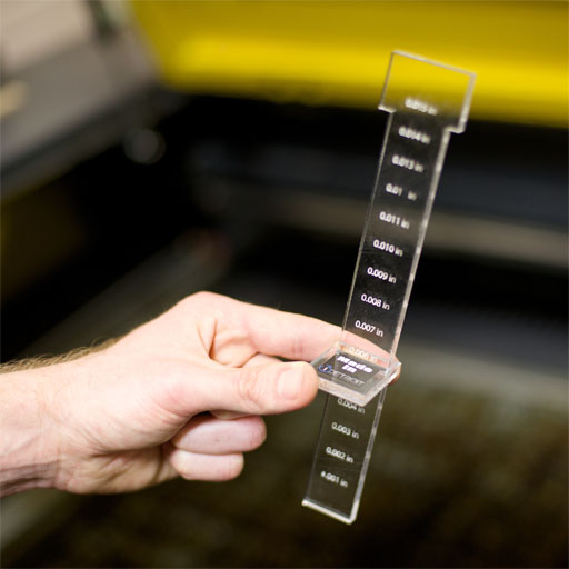
The result was this Kerf Taper Gauge. You simply cut the pattern with your desired material and settings, and drop the gauge through the hole in the tab. When the tapered gauge fits snugly, the taper of the gauge exactly compensates for the kerf, and you can read it off the label on the gauge. The measurement is averaged over 4 cuts: each side of the gauge and each side of the hole.
Next step: find a good way to correct for the kerf...
(Photo credit: Eric Merrill)
Copyright © Edward L. Platt 2011–2024
